How I made my 3D home page animation
I wanted to throw together a post on how I made the 3D spinning animation seen on my current (2020) home page because it ended up significantly more challenging than I expected. This was my first time using three.js, or dealing with 3D objects in the browser, and I learned a lot!
A gif of the 3d model from my current home page.
View an editable version of the project here or at the very bottom of the page.
Background
The motivation to redesign my website’s landing page originally came from Jonathan Zong’s portfolio, which features an interesting infinite animation (you can also see the color inspirations that I took from his site). I found myself spending many minutes on the home page, just watching the interesting patterns that were drawn on the screen. I had always been a sucker for small, interesting landing pages like these, and wanted to create one of my own.
As I searched for inspirations of what kind of landing page I wanted, I paid many visits to Dwitter (JavaScript visualizations written in 140 characters or left) and Awwwards (web design awards). Specifically, on Awwwards, there are many crazy interesting websites that use three.js, a 3d JavaScript library, to create visuals I could not believe were possible inside of a browser. Since high school, I had been in awe of websites such as this, and I decided that I would use this small project as a way to learn the basics of three.js.
I wanted to model something that wasn’t too hard for my first attempt, but ideally more complex than a simple cube. I settled on the Circle with Towers Sculpture by Sol LeWitt, which sits outside of the computer science building at the University of Texas. Before the pandemic, I saw that sculpture nearly every day and often felt like I spent more time inside of that building than my own apartment. More importantly, however, it had a seemingly simple geometry that I felt would be a good starting point to learn three.js.

A photo of the actual sculpture on the University of Texas campus
Development
I started by watching a Youtube video about three.js that gave a great introduction to the basics and got me up and running with the library very quickly. I also referenced much of the documentation found on the official three.js website because there are many options to choose from when it comes to lights, cameras, materials, shapes, etc.
Scene Setup
All objects and lights in three.js exist in a scene. A scene also has other properties that can be tweaked for specific use cases. I’ll step through the different parts of my code to explain what is going on with each chunk.
Global variables
const shapeColor = 0xc7b9ff;
const edgeColor = 0xc7b9ff;
const bgColor = 0xffffff;
const singleGeometry = new THREE.Geometry();
Here I define the colors (hex values) that I will be using throughout the project, as well as a single three.js geometry, because I am only going to be displying one object in the scene.
Scene, camera, renderer, and material
// Construct three.js objects
const scene = new THREE.Scene();
const camera = new THREE.PerspectiveCamera(
  75,
  window.innerWidth / window.innerHeight,
  0.1,
  1000
);
const renderer = new THREE.WebGLRenderer({ antialias: true });
renderer.setClearColor(bgColor);
renderer.setSize(window.innerWidth, window.innerHeight);
document.body.appendChild(renderer.domElement);

const material = new THREE.MeshLambertMaterial({
  color: shapeColor,
  opacity: 0.05,
  transparent: true,
});
I create a scene which is required to show any three.js object. I also set up the perspective camera, which is more natural than other camera types. When constructing it I define the field of view, aspect ratio, near plane, and far plane. This determines what the camera sees, and prevents the rendering of objects that are too close, or too far from the virtual camera.
I define a renderer that will actually display the scene. Anti-aliasing reduces jagged edges in curved objects and makes the animation look much smoother. I also set the background color to white, the size to the full screen, and append the renderer to the dom so that the scene can be displayed on the web page.
Finally, I set up the material, which is transparent purple that allows for the see-through effect.
Lights, camera, some action
// Set camera
camera.position.z = 5;
const controls = new THREE.OrbitControls(camera, renderer.domElement);
controls.enableDamping = true; // Make panning smoother

// Add a light
const light = new THREE.PointLight(0xffffff, 1, 500);
light.position.set(10, 0, 25);
scene.add(light);
Because I wanted the user to be able to rotate and zoom in/out on the scene, I included OrbitControls, which handles user interaction automatically.
Here I also add a white light with full intensity and a distance of 500.
Browser resizing
// Handle browser resize
window.addEventListener("resize", () => {
  renderer.setSize(window.innerWidth, window.innerHeight);
  camera.aspect = window.innerWidth / window.innerHeight;
  camera.updateProjectionMatrix();
});
This code is a handler for when the browser size is changed by the user. Without it, the scene will become distorted when the window becomes larger or smaller.
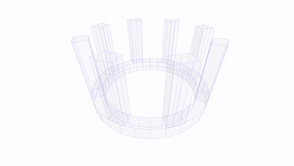
Model Geometry
Because of the pandemic, I was not in Austin at the time I created this webpage and sought to model the sculpture without any actual measurements. However, the original sculpture artist used blocks throughout this entire sculpture, which made it possible for me to count the blocks and get semi-accurate ratios for the model.

Labeled photo of the dimensions in ‘blocks’
Note: I will refer to the bottom ring of the sculpture as the base, and the 8 extrusions as the pillars.
Calculating base dimensions
After some experimentation, I found 0.1 was an appropriate size to represent 1 block, and based all other calculations off of that.
const block = 0.1;
const circumference = 96; // in block units
const pillarDim = 4; // in block units
const pillarHeight = 17; // in block units
const baseHeight = 4; // in block units
const cylinderInnerRadius = (circumference * block) / 2 / Math.PI;
const cylinderOuterRadius = cylinderInnerRadius + pillarDim * block;
const numCurves = 16; // more angled look to the sculpture
Due to the variance of concrete between blocks, both the inner and outer diameter of the base of the sculpture are 96 blocks, despite clearly being different sizes. However, I decided to use only use the blocks with a small concrete gap for measurements, as all the blocks that determine height in the sculpture have small gaps (this will also become relevant later when determining the length of a pillar). Thus, the inner radius (with minimal concrete) of the sculpture is found with the formula (circumference * block) / 2 / Math.PI, which just uses the basic circumference formula of 2πr, solving for r, and multiplied by the pre-determined block measurement. The outer radius must be 4 blocks greater than the inner one (4 blocks is the width of the base ring, whose blocks have minimal concrete), which leads to the formula cylinderInnerRadius + pillarDim * block.

A zoomed-in picture showing the difference in gaps between blocks. I only used block measurements with small concrete gaps.
Creating base geometry
// Base
const extrudeSettings = {
  depth: block * baseHeight,
  bevelEnabled: false,
  curveSegments: numCurves,
};

const circle = new THREE.Shape();
circle.absarc(0, 0, cylinderOuterRadius, 0, Math.PI * 2, 0, false);

const holePath = new THREE.Path();
holePath.absarc(0, 0, cylinderInnerRadius, 0, Math.PI * 2, true);
circle.holes.push(holePath);

const cylinder = new THREE.ExtrudeGeometry(circle, extrudeSettings);
const base = new THREE.Mesh(cylinder, material);
singleGeometry.merge(base.geometry, base.matrix);
Here I define a cylinder by creating a circle with cylinderOuterRadius and create a hole with cylinderInnerRadius. I then can extrude the shape 4 blocks high to create the base. Once the object is created I add it to the geometry I am using to contain all 3d objects.
Some technical notes here because it will keep coming up in later code snippets:
absarc()is a way to draw an arc by providing the following parameters (in order):- x, y – The absolute center of the arc.
- radius – The radius of the arc.
- startAngle – The start angle in radians.
- endAngle – The end angle in radians.
- clockwise – Sweep the arc clockwise. Defaults to false.
THREE.Path()- A 2D representation of a contour.THREE.Shape()- Defines an arbitrary 2d shape plane using paths with optional holes.THREE.ExtrudeGeometry()- Takes in a shape and extrusion settings to create a 3d object.Three.Mesh()- Takes in a 3d object and material so an object can be rendered.
Calculating pillar dimensions
At this point, I ran into a problem computing how far apart the pillars should be. Since the distance between pillars was not clear due to the variation in concrete spacing between blocks, I had to come up with another way to calculate the measurements. Also, remember that the width of the pillar is not a single measurement, since the whole pillar is a subsection of a cylinder with a hole in it.

Representation of the top of a single pillar
In order to do this, I used a ratio between the pillars and the gaps between them. I knew there are 8 pillars and 8 gaps between pillars, with each gap being exactly as large as two pillars. Another way to think of this is that there is room on the base for 24 appropriately sized pillars. Using this I divide the geometry into sections of 24 and extrude every third segment. For each pillar, I need to determine the outer arc and inner arc that will make up the face of the pillar, which can then be extruded.
const numPillars = 8;
const pillarLength = Math.PI / 12;
let pillarStart = 0;
let pillarEnd = pillarLength;

for (let i = 0; i < numPillars; i++) {
  // Get the two arcs that form the pillar
  const outerPillarShape = new THREE.Shape();
  outerPillarShape.absarc(0, 0, cylinderOuterRadius, pillarStart, pillarEnd, 0, false);
  const innerPillarShape = new THREE.Shape();
  innerPillarShape.absarc(0, 0, cylinderInnerRadius, pillarStart, pillarEnd, 0, false );

  ...

  pillarStart += pillarLength * 3;
  pillarEnd += pillarLength * 3;
}
Since the length of an arc is determined by it’s startAngle and endAngle (in radians), I ensure that the endAngle - startAngle for each pillar is equal to 1/24th of cylinderOuterRadius for the outer arc of the pillar, and 1/24th of cylinderInnerRadius for the inner arc of the pillar. This is where the expression const pillarLength = Math.PI / 12; comes from - it is a simplification of the formula 2π / 24. Remember that 2πr is the value in radians of a complete circle, but the r here is specified as a separate parameter in absarc(). In order to get the arcs for the next pillar, I increment the startAngle and endAngle by pillarLength * 3, skipping forward by 3/24 of the base geometry.
Great! I now have the arcs for the inner and outer curve of all of the pillars, now how do I combine them to make a single 3d object? Next, I’ll go through the ... section which was omitted in the above code.
Creating Pillar Geometry
...
// Get the vertices from the two arcs
  const vertices = [];
  const outerVertices = outerPillarShape.extractPoints().shape;
  const innerVertices = innerPillarShape.extractPoints().shape.reverse();
  for (let i = 0; i < outerVertices.length; i += Math.floor(numCurves / 2)) {
    vertices.push(outerVertices[i]);
  }

  for (let i = 0; i < outerVertices.length; i += Math.floor(numCurves / 2)) {
    vertices.push(innerVertices[i]);
  }

  // Extrude the shape
  const pillarShape = new THREE.Shape(vertices);
  const pillarGeo = new THREE.ExtrudeGeometry(
    pillarShape,
    pillarExtrudeSettings
  );
  const pillar = new THREE.Mesh(pillarGeo, material);
  pillar.translateZ(block * baseHeight); // offset the base height

  // Add to the sculpture group
  pillar.updateMatrix();
  singleGeometry.merge(pillar.geometry, pillar.matrix);
...
I found no easy way of using three.js to create a shape based on line segments. However, THREE.Shape() can take in a list of vertices to construct a shape, and so my solution was to create one face of the pillar by combining a list of the outer vertices and inner vertices. This leaves me with a closed shape that can be extruded just like the base of the sculpture. I use Math.floor(numCurves / 2) to skip some of the vertices in the arcs so that the wireframe will be less busy and make the arcs more angular.
Putting it all together
I now have both the base and the pillars of the sculpture, so all that’s left is to put them together and render them in the browser!
const singleBufGeometry = new THREE.BufferGeometry().fromGeometry(
  singleGeometry
);
const mergedMesh = new THREE.Mesh(singleBufGeometry, material);

// Create object group
const sculpture = new THREE.Group();
sculpture.add(mergedMesh);
const edges = new THREE.EdgesGeometry(singleBufGeometry);
const lines = new THREE.LineSegments(
  edges,
  new THREE.LineBasicMaterial({ color: edgeColor })
);
sculpture.add(lines);
sculpture.rotation.x = -0.9; // Tilt the sculpture forward
scene.add(sculpture);
I create a bufferGeometry() representations of the geometry, which is more efficient and causes less GPU strain than traditional three.js geometry. In order to display the line geometry of the object to accomplish the wireframe effect, I extract the edges from the geometry and use THREE.LineSegments() to style them. Finally, I can render the entire scene.
const clock = new THREE.Clock();

// Render the scene
const render = () => {
  const elapsedTime = clock.getElapsedTime();
  requestAnimationFrame(render);
  controls.update();
  sculpture.rotation.z = elapsedTime / 10; // Slowly tilt the structure on each frame
  renderer.render(scene, camera);
};

render();
Using THREE.Clock, we can ensure that the rotation of our object is the same speed regardless of the FPS of the monitor our website is displayed on.
Animations
After creating the object, I wanted to create some kind of interesting animation to further display and experiment with the cool aspects of 3d rendering in the browser. I used GreenSock Animation Platform or GSAP for an animation whenever a user clicks the ‘About’ button on the home page.
controls.reset();
this.tl = new TimelineMax().eventCallback("onComplete", () => {
  zoomed = true;
  inProgress = false;
});
this.tl.to(sculpture.position, 2, { x: -2.5, ease: Expo.easeOut });
this.tl.to(sculpture.rotation, 1, { x: 0, ease: Expo.easeOut }, "=-2");
this.tl.to(camera.position, 1, { z: 3, ease: Expo.easeOut }, "=-2");
this.tl.to(
  document.getElementById("about-info"),
  1,
  { opacity: 1, display: "block" },
  "=-2"
);
This code creates a timeline this.tl upon which I can define events that happen in a specific order. The to() events alter the properties of the sculpture object (which contains all geometry and edges). I specify the specific sculpture object to alter, the duration of the animation, a set of keys and values to change and their easing animations, and finally the animation offset to change when the animation starts (normally events happen sequentially).
First, this animation resets the controls because the object could be zoomed or rotated by user input. It then simultaneously rotates the sculpture up, moves it to the left side of the page, zooms in the camera closer to the object, and displays the about animation. After the animation, it sets some variables to allow the about section to be closed. Similarly, the code to reverse this animation is:
controls.reset();
this.tl = new TimelineMax().eventCallback("onComplete", () => {
  zoomed = false;
  inProgress = false;
});
this.tl.to(sculpture.position, 2, { x: 0, ease: Expo.easeOut });
this.tl.to(sculpture.rotation, 1, { x: -0.9, ease: Expo.easeOut }, "=-2");
this.tl.to(camera.position, 1, { z: 5, ease: Expo.easeOut }, "=-2");
this.tl.to(
  document.getElementById("about-info"),
  0.5,
  { opacity: 0, display: "none" },
  "=-2"
);
Which basically does the same thing as before, but restores the properties to the original settings.
Conclusion
As you can probably tell by the length of this write-up, this three.js experiment took much longer than I was expecting. I spent many hours googling an out-of-the-box solution for how to better create the pillars but ended up having to draw a lot of pictures, count a lot of blocks, and try many different approaches before I found one that was relatively clean and efficient.
Overall I am really happy with how the project turned out. I learned a lot about three.js and have really enjoyed being able to show off my fancy new website to professors and fellow students in college, who all miss the computer science building to varying degrees.
If you have any questions or suggestions please shoot me a message on any of the contact options linked in the footer of my blog!
I would love for other people to take a look at the project and mess around with it here:
See the Pen GDC Three.js by Levi Villarreal (@leviv) on CodePen.